Beam Stiffness Calculator
Flexural Stiffness Result
Enter values and click Calculate
Common Construction Materials
Key Takeaways
- Stiffness measures how much a component resists deformation under load.
- Young's modulus, moment of inertia and cross‑section shape are the three main drivers of structural stiffness.
- Deflection limits, vibration control and safety factors are practical design checks that stem from stiffness calculations.
- Finite element analysis lets engineers predict stiffness early in the design process for complex geometries.
- Choosing the right material and section size can save cost while meeting stiffness requirements.
When a building or a bridge sways, cracks, or feels “soft” under foot traffic, the culprit is often inadequate engineering stiffness. Understanding how stiffness works, how to calculate it, and why it matters can turn a shaky concept into a solid design decision.
What is Stiffness?
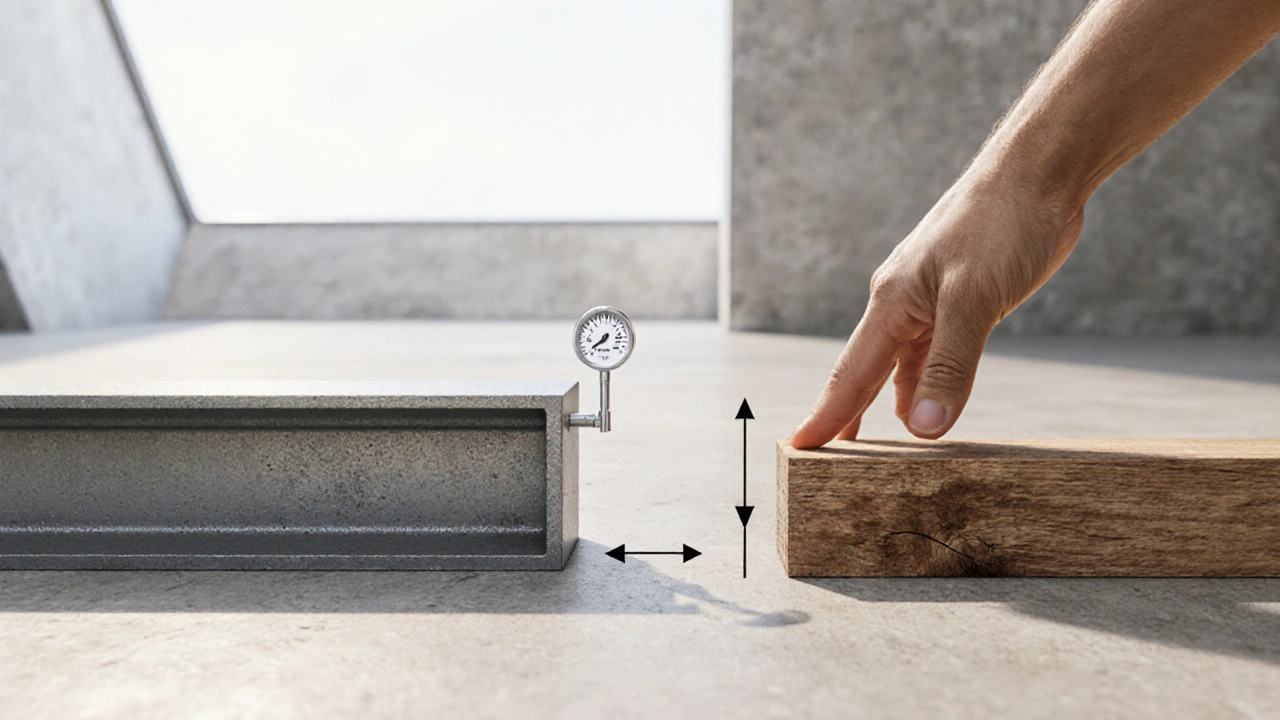
Stiffness is the resistance of a structural element to deformation when a force is applied. In everyday language it’s the feeling you get when you press on a steel beam versus a wooden plank - the steel bends far less. In engineering, that “resistance” is quantified so we can predict how a component will behave under real loads.
How Do We Quantify Stiffness?
The simplest way is the spring‑constant relationship, familiar from basic physics:
k = F / δ, where k is the stiffness (N/m), F is the applied force and δ is the resulting deflection.
For beams and columns, two material properties dominate the equation:
- Young's modulus is a measure of a material’s intrinsic elasticity, expressed in gigapascals (GPa). It tells us how stiff the material itself is.
- Moment of inertia is a geometric property that reflects how a cross‑section resists bending, measured in mm⁴. A deeper or wider section boosts this value dramatically.
When you combine a material’s Young's modulus (E) with the moment of inertia (I) for a given length (L), the flexural stiffness of a beam becomes EI/L. The higher the EI product, the less the beam will sag under load.
Why Stiffness Matters in Design
Design codes around the world set service‑ability limits that are directly tied to stiffness:
- Deflection limits: A floor that deflects too much may cause cracking of finishes or discomfort for occupants. Typical limits are L/360 for concrete slabs and L/500 for steel floors.
- Vibration control: In long-span bridges or mezzanine floors, excessive flexibility can lead to noticeable vibration under foot traffic. Engineers calculate natural frequencies using stiffness and mass to keep them out of the uncomfortable range.
- Load distribution: Stiffness determines how loads are shared among parallel members. A stiff girder carries most of the load, while a flexible one takes less, which influences sizing of connections.
Ignoring stiffness can result in costly retrofits, service complaints, or even structural failure.
Material Choice and Section Geometry
Different construction materials offer wildly different stiffness values. Below is a quick look at the typical ranges you’ll encounter.
| Material | Young's Modulus (GPa) | Typical Stiffness (kN/m per m³) | Common Uses |
|---|---|---|---|
| Structural Steel | 200 | ≈ 30,000 | High‑rise frames, bridges |
| Reinforced Concrete | 30 | ≈ 4,500 | Foundations, parking decks |
| Timber (Glulam) | 12 | ≈ 1,800 | Sport arenas, aesthetic façades |
| Aluminium | 70 | ≈ 10,500 | Lightweight roofs, curtain walls |
Besides material, the shape of the cross‑section can boost stiffness without adding mass. For instance, an I‑beam offers a moment of inertia many times higher than a rectangular tube of the same weight because the material is concentrated away from the neutral axis.
Computational Tools: Finite Element Method
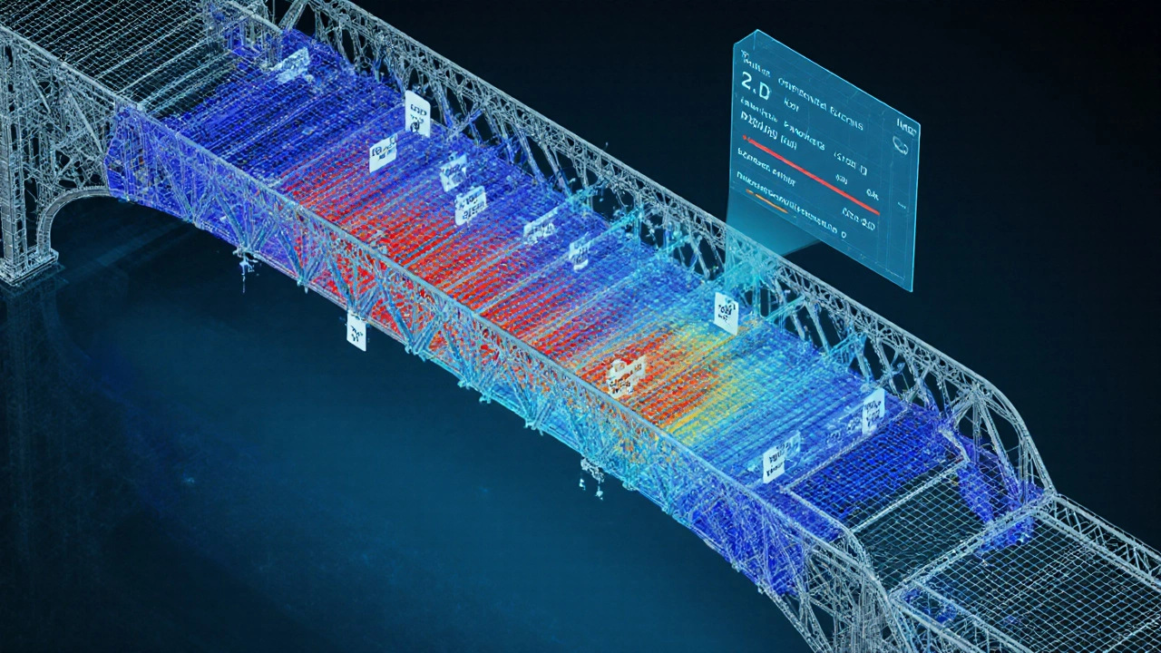
When structures become complex-think curved steel shells, irregular concrete cores-hand calculations become impractical. Finite element method is a numerical technique that divides a structure into small elements, solving stiffness equations for each and assembling them into a global system. Modern software (ETABS, SAP2000, ANSYS) can output a full stiffness matrix, so engineers can see exactly where the model is flexible and where it’s rigid.
Key steps in an FEA workflow:
- Model geometry and assign material properties (E, Poisson's ratio).
- Choose appropriate element types (beam, shell, solid).
- Apply loads and boundary conditions (Load is any external force, pressure or moment acting on the structure).
- Run the solver to obtain nodal displacements and element forces.
- Check computed deflections against code limits and assess vibration frequencies.
The output includes a visual map of stiffness-areas that bend more appear in warmer colors, guiding designers to add reinforcement or change section shapes.

Real‑World Examples
Example 1: Long‑Span Pedestrian Bridge
A 30‑metre steel truss bridge in Melbourne was initially designed with shallow members to save material. During the FEA stage, engineers saw a first natural frequency of 3.2Hz, which coincided with the typical walking frequency (2‑3Hz). That meant pedestrians would excite the bridge, causing noticeable bounce. By increasing the depth of the top chord (boosting I) the frequency shifted to 5.1Hz, eliminating the vibration issue without adding significant weight.
Example 2: High‑Rise Office Tower
The 45‑storey tower in Perth used a composite steel‑concrete floor system. Designers set a deflection limit of L/500 for the slab. By selecting a concrete grade of 40MPa (E ≈ 33GPa) and a 200‑mm thick slab with steel reinforcement, the calculated slab stiffness met the limit, allowing a slimmer floor height and saving millions in construction cost.
Common Pitfalls & How to Avoid Them
- Ignoring connection flexibility: Even if a beam is stiff, a flexible bolt‑grid can introduce extra rotation. Model connections with appropriate stiffness values or use semi‑rigid element types.
- Over‑relying on code‑prescribed sections: Codes give minimum sizes, but the most economical solution often comes from an iterative stiffness‑weight trade‑off. Run a parametric study in your FEA model.
- Forgetting temperature effects: Materials expand or contract, altering effective stiffness in long members. Include thermal loads when designing bridges or pipelines.
- Mis‑interpreting EI: A high Young's modulus can be offset by a poor cross‑section shape. Always compute the product EI, not E alone.
Quick Design Checklist for Stiffness
- Identify critical members where deflection limits drive the design.
- Calculate or obtain material Young's modulus.
- Compute moment of inertia for the chosen cross‑section.
- Derive flexural stiffness (EI) and compare against service‑ability requirements.
- Run a simple FEA model to capture secondary effects (connections, non‑uniform loads).
- Check natural frequencies if vibration‑sensitive usage is expected.
- Iterate: adjust material grade or section depth until targets are met while keeping weight and cost reasonable.
Frequently Asked Questions
How is stiffness different from strength?
Strength tells you how much load a material can carry before it fails, while stiffness tells you how much it will deform under a given load. You can have a very strong material that is still quite flexible (like high‑strength steel with a thin profile), and a stiff material that yields at low loads (like a thick timber beam that bends very little but may crack early).
What is the typical deflection limit for a concrete floor?
Most building codes prescribe a limit of L/360 for reinforced concrete floor slabs, where L is the span length. For a 6‑metre span, that translates to a maximum vertical deflection of about 17mm.
Can I increase stiffness without adding more material?
Yes. Changing the shape of the cross‑section is the most material‑efficient way. Moving material away from the neutral axis-using I‑beams, hollow sections, or adding flanges-raises the moment of inertia dramatically, boosting stiffness while keeping weight low.
When is it necessary to perform a vibration analysis?
Any structure that experiences dynamic loads-foot traffic, machinery, wind, or seismic activity-should have a vibration check. Bridges, mezzanine floors, tall slender towers, and industrial equipment platforms are common candidates.
How does temperature affect stiffness?
Temperature changes cause materials to expand or contract, altering their modulus slightly. For long steel members, a 30°C swing can change stiffness by up to 2%, which may be critical for precision bridges or pipelines. Include thermal expansion coefficients in your analysis when temperature variation is anticipated.

Patrick Price
Yo, I was playing with that beam stiffness calculator and realized you can actually mess up the units real quick – got my result in kN/m when I needed N/mm and it looked like I was reading a sci‑fi novel. Also, the input fields are kinda cramped, defintely could use some padding. The whole thing feels like it was designed by someone who hates whitespace. Anyway, good start though, just needs a bit of polish.
Travis Evans
Haha, love the hustle! 🎉 You nailed the point about the unit confusion – totally the kind of thing that trips up the newbies. If they added a tiny tooltip next to the dropdown, it’d save a lot of head‑scratching. Keep the fire alive, the community thrives on tweaks like this.
Jessica Hakizimana
Stiffness isn’t just a number; it’s the bridge between imagination and reality.
When you feed the calculator with realistic values, you’re actually shaping the future of a skyscraper before the first steel beam is cut.
Imagine a child's swing set – a flexible vine versus a rigid pole – the experience changes entirely.
Engineers use flexural stiffness to ensure that bridges sway just enough to feel alive but not so much that they frighten pedestrians.
Even in aerospace, the same principles guarantee that wings carry loads without fluttering dangerously.
What’s fascinating is how material selection – steel, timber, aluminium – each writes its own story in the stiffness equation.
Choosing a high‑modulus steel can make a slender column feel stout, while a bamboo beam tells a different tale of flexibility.
The calculator’s ability to switch units on the fly empowers designers to think in both metric and imperial mindsets.
When you adjust the moment of inertia, you’re effectively redefining a structure’s resistance to bending.
This can be a game‑changer for retrofits where space constraints demand clever geometry.
Remember that stiffness isn’t static; temperature, aging, and moisture can subtly shift E and I over time.
Thus, periodic re‑evaluation using tools like this keeps safety margins intact.
In the grand scheme, every line of code that simplifies stiffness computation adds a brick to the edifice of sustainable design.
So keep feeding it data, experiment, and let the numbers guide your creative engineering journey.
Stay curious, stay bold, and let stiffness be your compass.
peter derks
Right on, that calculator is a solid side‑kick for quick checks! I love how you can pop in the Young's Modulus and instantly see the effect on flexural rigidity. It’s like having a pocket‑sized structural lab. The layout feels snappy, and the result field updates instantly – perfect for those brainstorm sessions. Keep the momentum going, maybe throw in a graph next time?
Sarah DeMaranville
Honestly the tool feels overly simplistic; seasoned engineers scarcely need such a basic interface.
Edward Leger
The notion of stiffness as a design parameter is profound yet often overlooked. By quantifying it, we gain insight into load distribution and deflection limits. However, the calculator omits considerations like shear deformation, which could be relevant in deep beams.
Keyla Garcia
OMG this is 🔥! Who knew numbers could look this sleek? The calculator vibes with my design mood board, and the instant result is pure satisfaction. Keep slaying, devs! 😎🚀
Ismaeel Ishaaq
Brilliant work! The ability to toggle between kN/m and N/mm instantly bursts open new horizons for cross‑regional collaborations. I’ve already tossed the results into a larger finite‑element model and the consistency is spot‑on. Keep pushing the envelope – the world needs more tools that marry precision with user‑friendliness.
Jesse Goodman
Great tool, very intuitive 😊
Antara Kumar
The calculator serves its purpose but the interface could be streamlined; unnecessary elements distract from core functionality.
John Barton
Wow, a calculator for stiffness? How original – next you'll tell us how to add two numbers. 🙄 Nonetheless, if it saves a rookie from a coffee‑break panic, kudos to the effort.